Tuesday, April 3, 2018

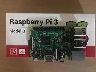
Raspberry Pi with Pi Camera

Raspberry Pi with Pi Camera

In this module, I will describe on how to connect and use Pi Camera with Raspberry Pi.

Requirements:

1. Raspberry Pi .


2.  HDMI Cable connected to a TV/ Monitor.

3. A Raspberry Pi , Pi NoIR V2 Camera.


4. A  wired keyboard.


5. A wired USB mouse.


Connecting Pi camera with Raspberry Pi:


1. Follow the steps on my previous blog on how to connect a Raspberry Pi with Smart TV here .

2.  Open up your Raspberry Pi Camera module. Be aware that the camera can be damaged by static electricity. Before removing the camera from its grey anti-static bag, make sure you have discharged yourself by touching an earthed object (e.g. a radiator or PC Chassis).

3.  Install the Raspberry Pi Camera module by inserting the cable into the Raspberry Pi. The cable slots into the connector situated between the Ethernet and HDMI ports, with the silver connectors facing the HDMI port.


4. Boot up your Raspberry Pi.

5. From the prompt, run "sudo raspi-config". If the "camera" option is not listed, you will need to run a few commands to update your Raspberry Pi. Run "sudo apt-get update" and "sudo apt-get upgrade".

6. Run "sudo raspi-config" again - you should now see the "camera" option.


7.  Select Interfacing Options.


8. Select Camera


8.  Enable the Camera.


9.  Select “Finish” and reboot your Raspberry Pi.

Launching camera to take pictures:


Pictures can be taken via two ways:

      1.  By command  line interface "raspistill".(Needs no programming knowledge)

This is inbuilt command interface that can be used to take pictures wthout any prior knowledge of any programming language. To capture an image in jpeg format, type "raspistill -o image.jpg" at the prompt, where "image" is the name of your image.

      2.  By python script.

Steps:


      a.)  From the Pi Home screen launch the terminal.

      b.)  Run "cd Desktop/" and then "nano cameraexample.py"

      
      c.)  Type the below code into the editor and save it.


import time import picamera camera = picamera.PiCamera() camera.Capture('image.jpg')

Note: Follow the link https://wiki.gentoo.org/wiki/Nano/Basics_Guide if you are a newbie to nano editor.

  d. ) Save the file and from terminal Run "python cameraexample.py". You will now see a image file created with the name "image.jpg" on the Desktop. Open this file. This is your captured image.


Raspberry Pi with Samsung Smart TV

Raspberry Pi with Samsung Smart TV


In this blog, I will cover about steps to connect  Samsung Smart TV with Raspberry Pi .

Requirements:

 1. Samsung Smart TV with connected HDMI cable.

2.  Raspberry Pi module 

3.  A 5V micro USB power supply to power your Raspberry Pi. Be careful that whatever power supply you use outputs at least 5V; insufficient power will cause your Pi to behave in strange ways.

4. A USB wired keyboard.

5. A USB wired mouse.


Set Up:

  1. Download the NOOBS software from here.
  2. Extract the folder . It should look something like this:
        
       3. Format your SD Card with  SD Memory Card Formatter . (Note: You can  use any                 SD Card formatting tool or do it manually via Windows/Mac/Linux disk 
           management tool.)

      4. In the formatted SD Card, copy all the contents (as seen above) , in the SD Card.

      5. Insert the SD Card into the card slot on the Pi .

      6. Connect the HDMI cable (from the TV) to Pi HDMI slot.

      7. Switch on the TV and select Source as the HDMI cable connected. You might see a               "Unknown"next to the HDMI slot. This is your Raspberry Pi. Select this HDMI as        
          source.

      8. The complete Setup should look like this:


If you have any queries or issue in above issues. please add your comment below in the comment section


Saturday, March 31, 2018

7 Segment 4 digit display using Arduino MEGA 2560

In this blog we are going to demonstrate how to use 7 segment 4 digit display with a arduino Mega 2560 board.

Parts required:

1. Arduino MEGA 2560 board

2. Bread board


3. 7 Segment 4 digit with 12 pins.


4. Jumper wires.


5. A-Male to B-Male cable


6. 4 220 Ohms resistors (4)


Step 1: Download the Seven segment display controller library for Arduino : https://github.com/DeanIsMe/SevSeg/archive/master.zip
After downloading place it inside the library folder of your arduino IDE.
Make sure you will see content as follows.


Step2 : Please have a look at the pin diagram of 7 segment display – 4 digit (This is specific to the model i have mentioned above)


Really hard to find these details in net.
Now make the circuit as below

Note : Digit Pins
Pin 12 of 7 segment – D1 => pin 13 of arduino
Pin 9 of 7 segment –  D2 => 12 of arduino
Pin 8 of 7 segment -D3 => 11 of arduino
Pin 6 of 7 segment -D4 => 10 of arduino
Pin 11 of 7 segment -a => 2 of arduino
Pin 7 of 7 segment -b=> 3 of arduino
Pin 4 of 7 segment -c=> 4 of arduino
Pin 2 of 7 segment -d=> 5 of arduino
Pin 1 of 7 segment -e  => 6 of arduino
Pin 10 of 7 segment -f => 7 of arduino
Pin 5 of 7 segment -g => 8 of arduino
Pin 3 of 7 segment -p => 9 of arduino
Make sure to add 220 ohms of resistor for D1, d2, d3, d4 pins to regulate the current flow.
open arduino IDE and paste below code. If you need to know how to setup arduino IDE for first time , refer my previous post
/* SevSeg Counter Example
 Edited by Haneef Puttur to match SMA420564 (www.haneefputtur.com)
 Copyright 2014 Dean Reading
 
 Licensed under the Apache License, Version 2.0 (the "License");
 you may not use this file except in compliance with the License.
 You may obtain a copy of the License at 
 http://www.apache.org/licenses/LICENSE-2.0
 
 Unless required by applicable law or agreed to in writing, software
 distributed under the License is distributed on an "AS IS" BASIS,
 WITHOUT WARRANTIES OR CONDITIONS OF ANY KIND, either express or implied.
 See the License for the specific language governing permissions and
 limitations under the License.
 
 
 This example demonstrates a very simple use of the SevSeg library with a 4
 digit display. It displays a counter that counts up, showing 10 deci-seconds.
 */

#include "SevSeg.h"

SevSeg sevseg; //Instantiate a seven segment controller object

 void setup() {
 byte numDigits = 4; 
 byte digitPins[] = {10, 11, 12, 13};
 byte segmentPins[] = {2, 3, 4, 5, 6, 7, 8, 9};

sevseg.begin(COMMON_CATHODE, numDigits, digitPins, segmentPins); 
// If your display is common anode type, please edit comment above line and uncomment below line
// sevseg.begin(COMMON_ANODE, numDigits, digitPins, segmentPins);
sevseg.setBrightness(90);
}

void loop() {
 static unsigned long timer = millis();
 static int deciSeconds = 0;
 
 if (millis() >= timer) {
 deciSeconds++; // 1000 milliSeconds is equal to 10 deciSecond
 timer += 1000; 
 if (deciSeconds == 10000) { // Reset to 0 after counting for 1000 seconds.
 deciSeconds=0;
 }
 sevseg.setNumber(deciSeconds, 1);
 }

 sevseg.refreshDisplay(); // Must run repeatedly
}

/// END ///
Now compile and upload the program to arduino

upload

Raspberry Pi with Pi Camera

Raspberry Pi with Pi Camera In this module, I will describe on how to connect and use Pi Camera with Raspberry Pi. Requirements: ...